Electrical faults are rarely as simple as they first look. A dead window, a non-working fan or a warning light can come from a blown fuse, poor earth, damaged connector, failed relay or a control module that never receives the right signal. A wiring diagram gives me the circuit in a readable form, so I can trace the path, test the weak point and avoid throwing parts at the car. In this article I break down how I read the circuit, which tests I trust and the mistakes that usually waste time during diagnosis.
The fastest diagnosis starts with the circuit, not the part
- Identify the power, ground and load path before testing anything.
- Look for shared fuses, splices, relays and earth points, because one fault can affect several systems.
- On live circuits, voltage drop tells me more than continuity alone.
- Healthy battery voltage is usually about 12.4-12.8 V at rest and roughly 13.5-14.8 V while charging.
- Many network faults need data checks and pin-level tests, not just a visual inspection.
What a vehicle electrical schematic really shows
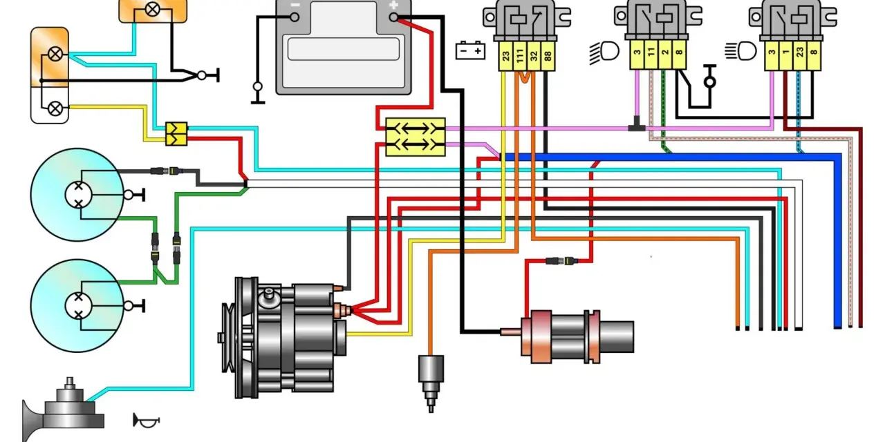
I treat a vehicle electrical schematic as a map of how current, commands and feedback move through the system. It is not just a drawing of wires; it shows me where power enters, where the circuit is switched, how the load is protected and where the return path goes back to ground. That matters because most electrical faults are not “random” at all - they usually sit on one side of that chain.
The symbols I look for first are the ones that tell me where to test:
- Battery feed - the source of power for the circuit.
- Fuse - protection against excess current; if it blows, I want to know why, not just replace it.
- Relay - a switch controlled by a low-current signal that lets a higher-current circuit operate.
- Switch or control module output - the part that commands the circuit on or off.
- Load - the component doing the work, such as a motor, lamp, solenoid or heater.
- Ground point - the return path; poor earths create more fake failures than many owners realise.
- Connector and pin numbers - the detail that saves time when I need to back-probe the right terminal.
- Splice - a shared junction where one feed or ground is divided to more than one circuit.
- Data line - a communication path such as CAN or LIN, where the issue may be information loss rather than missing power.
The practical limitation is simple: the page shows electrical logic, not always the full physical route in the car. For that reason, I pair the schematic with component location data and connector views instead of trusting the drawing alone. Once those building blocks make sense, the next step is to read the circuit with a test plan in mind.
How I read the circuit before I pick up a meter
When I open the diagram, I do not start by staring at every wire. I start with the symptom, then work backwards through the circuit until I know where the failure could live. That keeps the diagnosis focused and stops me from testing parts that are not part of the problem.
- Confirm the symptom under the same conditions the driver reported. A fault that happens only hot, only wet or only at idle often points in a different direction from a constant failure.
- Find every component that shares the same fuse, relay, earth point or splice. Shared parts are where I expect patterns.
- Trace the circuit from supply to load and from load back to ground. I want to see the full loop, not just the obvious half.
- Mark connector numbers and pin numbers before testing. Guessing at the wrong terminal is how good technicians waste time.
- Check whether the fault is local or shared. If several items fail together, I suspect a common feed, common earth or a communication issue.
For intermittent faults, I also look for the conditions the schematic cannot show: vibration, heat soak, water ingress and strain on the loom. On many UK-market cars, those four clues matter more than the badge on the grille, because the electrical architecture is often shared across models and trims. That is why I move from reading the circuit to proving it with tests.
The tests that prove the fault
Once I know where the fault could be, I test the circuit in sections. The goal is not to measure everything; it is to measure the right thing in the right place. A good diagnosis usually comes from three checks: supply, ground and signal.
| Circuit area | What I test | What looks healthy | What an abnormal result usually means |
|---|---|---|---|
| Battery feed and fuse | Voltage on both sides of the fuse with the circuit loaded | Close to battery voltage on both sides | Blown fuse, poor contact, overheated holder or upstream feed loss |
| Ground side | Voltage drop from component earth to battery negative | Very low drop, often around 0.1-0.2 V or less on a simple check | Corrosion, loose bolt, damaged terminal or hidden resistance in the earth path |
| Switch or relay control | Command voltage or ground from the control side | Matches the scan tool command and energises the relay when expected | Failed switch, module output issue, broken wire or control logic problem |
| Sensor or signal circuit | Reference voltage, signal voltage or waveform | Stable value that changes predictably with input | Open circuit, short to power, short to ground or corrupted signal |
| CAN or LIN network | Communication state, voltage behaviour and network integrity | Scan tool communication is stable and the network behaves as designed | Module power loss, bad earth, damaged twisted pair or network interruption |
For many high-speed CAN systems, about 60 ohms measured across the bus with the battery disconnected and the modules asleep is a common healthy reference, but I still check the exact target in service data because not every platform follows the same pattern. On live circuits, I prefer a multimeter for voltage drop and a test lamp for quick load checks. If the fault involves timing, pulses or communication quality, a scope becomes the better tool. The diagram helps me choose the tool instead of guessing at it.
This is where the real time saving happens: the schematic tells me which test will answer the question, and the test tells me whether the circuit is healthy under load. That leads directly to the biggest trap in electrical diagnosis, which is trusting continuity checks too early.
Why voltage drop usually beats continuity checks
Continuity checks are useful, but only when the circuit is dead and I want to know whether a path exists. They do not tell me how that path behaves under load. A wire with corrosion, a loose terminal or a heat-damaged splice can look fine on a continuity test and still fail the moment current flows.
That is why I use voltage drop so often. It shows me the resistance that matters in real operation, not just the resistance the meter sees in a near-zero-current test. On high-current circuits, even a few tenths of a volt in the wrong place can change the result from normal to fault.
- On the power side, I compare battery voltage to the voltage reaching the load.
- On the ground side, I compare the load earth to battery negative while the circuit is working.
- On the control side, I check whether the module or switch is actually commanding the relay or actuator.
That approach also stops me from replacing good parts. If the supply is strong, the ground is clean and the command signal is correct, the fault is more likely inside the component or in the logic that drives it. If one of those checks fails, I have a concrete direction instead of a guess. From there, the next step is avoiding the mistakes that make a simple circuit look complicated.
The mistakes that waste time on real diagnostics
The fastest way to lose an afternoon is to treat every electrical fault as if it were caused by the most expensive part on the circuit. I see the same errors again and again, and they all create false confidence.
- Chasing fault codes before the symptom - codes are clues, not proof of the failed part.
- Testing only with the battery disconnected - dead-circuit checks miss problems that appear under load.
- Ignoring earth points - bad grounds are responsible for a lot of “mystery” failures.
- Probing the wrong side of the connector - it is easy to test the harness and not the component, or the other way round.
- Replacing a module too early - if the feed or ground is poor, the module may be innocent.
- Forgetting shared circuits - one broken splice can disable several systems at once.
- Missing intermittent damage - heat, vibration and moisture can make a wire fail only part of the time.
My rule is simple: if I cannot show a fault with a test result, I do not call the part failed. That sounds obvious, but it is the difference between a repeat repair and a proper fix. Once I avoid those traps, I can use the schematic for the harder cases, where the fault is hidden deeper in the network or appears only under specific conditions.
When the schematic is not enough
Some faults sit outside the neat lines of the drawing. A module can be powered correctly and still fail because of software, calibration or an internal defect. A loom can pass a quick check and still open up when the engine moves or the car hits a bump. A network can appear dead because one module has lost power, not because the whole bus has collapsed.
At that point I widen the diagnosis instead of narrowing it too early. I check for:
- Power and ground at every relevant module, not just the one with the warning light.
- Communication integrity, especially on CAN and LIN systems where one bad node can disturb the whole network.
- Technical bulletins or known issues that match the symptom pattern.
- Harness movement, heat and moisture sensitivity when the fault is intermittent.
- Mechanical causes that mimic electrical failure, such as seized motors, water ingress or weak batteries.
This is also where guided component tests and scope captures become valuable, because they let me compare the real signal with what the circuit should be doing. A schematic stays central, but it becomes one part of a broader diagnostic method rather than the whole answer. The last step is making sure the repair still holds when the car is back in normal use.
The last checks I make before I hand the car back
When the repair looks complete, I do not stop at “the fault is gone”. I recreate the original conditions, clear the codes, run the circuit under load and confirm that the symptom does not return. If the fault was intermittent, I wiggle the harness, heat the area if appropriate and road test the vehicle long enough to catch a weak connection that only shows itself once everything warms up.
I also check the simple things that protect the repair: connector locks seated properly, terminals not spread, loom routed away from sharp edges and hot components, and the correct fuse rating fitted. That final pass takes minutes, but it is what separates a temporary fix from a repair I would trust. If I have done the job properly, the schematic has done more than explain the circuit - it has shown me exactly how to prove the repair was worth making.